Designing an Orrery
Preface
As this is part of a project portfolio, I wanted to define the problem for the project, show a logical design process, display my capabilities, reveal the outcome, and share what I learned.
At the same time, I also hope my design process, background research, and ideas can be a reference that helps others design their own orreries; this means the content is sometimes a bit technical. (If you want to skip the design process and use someone else’s existing gear ratios, you may want to instead just follow instructions from Instructables.)
Motivation
As a child, I remember attempting to build a Lego model of the solar system, but I was never fully satisfied. Having learned about mechanical design, I decided to revisit this aspiration in college.
Personally, I also find orreries beautiful, both for their mechanisms and for their artistry. I was particularly inspired by orreries from Ken Condal (Zeamon)1, Staines & Son Orrery Makers2, Paul Bambrick Finescale Modelling3, and a student team from the University of Colorado Bolder4.
Historical reasons for mechanical astronomical models
For centuries, as both an educational tool and as technical skill demonstration of a business or clockmaker, people have constructed mechanical astronomical models under a variety of names (orreries, planetariums, tellurians, and more).
Problem
My priority was to design an orrery with better accuracy of the relative motion of the planets through the application of modern computational and manufacturing tools.
I also wanted to make it easy to continue iterating in the future, creating newer versions of the system. This favored free and open source software, automation of design changes, and use of readily available manufacturing processes.
Project Constraints
- I was a student. It had to differentiate itself from the current state of the art and contribute to the field.
- I did not have
- time to cut the gears by hand
- the budget or access to CNC or manual machining equipment
- I had access to
- my personal tools,
- Open Hardware Makerspace
- the NCSU Hunt Library Makerspace5
- a great local hardware store6
- online parts catalogs
- online custom fabrication services (Shapeways7, etc) as I could afford.
Avoiding Feature Creep
With a self-directed project like this, I had to resist a tendency to explore and pursue “side quests”. ( “Yak shaving” refers to a related practice.) I enjoy learning and making a project even better, but this makes projects take longer. In this particular case, I had a hard deadline because I decided to turn the project into an academic one. Therefore, I deliberately left some paths untraveled:
- I used sidereal periods calculated by others, rather than deriving them myself for a particular date range from ephemeride data. The derivation of sidereal periods is discussed further in a footnote for a later section.
- All orbits were represented as circular and coplanar, rather than as elliptical with inclination.
- Planet tilt, moons, and rotations of the planets or sun were not addressed.
- Rather than creating a script completely myself, I used an existing OpenSCAD involute gear script to create my teeth profiles.8 (I did have to modify it to generate stub teeth profiles; stub teeth are less delicate with small numbers of teeth.) The number of possible gear ratios increases when the minimum number of gear teeth decreases.
- I manually packed the laser cut parts onto sheets rather than automating it.9
- Ornamenting the face of each gear with fractals or other generative art would have added work unrelated to the mechanical design, so I left them unadorned.
Gear Selection
Target Ratios and Significant Figures
I used the sidereal periods to calculate the desired ratios between planets. One key was finding sources with a large number of significant figures. The periods I used are listed below and are found in multiple sources. Some other orreries may be based on other sources and values.10
| Planet | Sidereal Period (Julian years) |
|---|---|
| Mercury | 0.2408467 |
| Venus | 0.61519726 |
| Earth | 1.0000174 |
| Mars | 1.8808476 |
| Jupiter | 11.862615 |
| Saturn | 29.447498 |
| Uranus | 84.016846 |
| Neptune | 164.79132 |
| Pluto | 247.92065 |
The fabricated system’s gear ratios are exact mathematical quantities, so they are not a limiting factor in the number of significant figures.11 To avoid cumulative rounding errors, when computing the ratios between planets and the accuracy of the mechanical design, significant figure rounding was not done until after the calculations were complete.
System Design
The distribution of the list of available gear ratios (with various constraints) showed the frequency of unique gear ratios was greatest near 1:1. This is significant because the maximum error decreases when the available gear ratios are closer together. The distance between each next available gear ratio can can be used to predict the maximum error magnitude (at a particular gear ratio).12
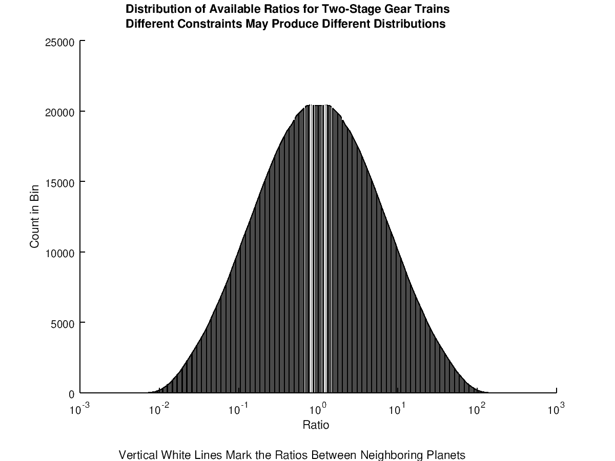
Because swapping the gears inverts the ratio, the graph is symmetric about a 1:1 ratio.
This type of information also helped me strategize on how to structure the gearing. The gear system connectivity can be represented graphically. Planets (and, if present, auxiliary axes) are represented as nodes. A train of gears between a pair of nodes is represented as an edge. The edges are undirected because power can be transmitted along a gear train in either direction.
The graph should be connected and acyclic (no loops). The first requirement (connected) allows a single power source to drive all the nodes. Because a single path from a power source is sufficient to drive any node, adding a loop of intermeshed gears (a “constrained gear system”) would not drive a node better, but would add complexity, require more precision in manufacturing, and be more likely to jam.
This limits the possible gear systems to those that can be represented by a tree graph. The number of possible trees grows rapidly as the number of nodes increases, as defined by Cayley’s Formula (nn-2). Because of the size of this number, I decided what trees to consider based on the distribution of gear ratios and a desire to limit the system size and keep fabrication and assembly simple.
The two structures that seem to be used most widely are depicted here (only the first few planets are shown). These trees show how the gear rotations are connected. In the first tree, each planet is driven consecutively off of the previous planet's motion. In the second tree, a single auxiliary axis rotates and powers several planets.
I used a variation of the second approach, with separate auxiliary axes for Mercury through Jupiter and for Jupiter through Pluto. In my particular case, I used two-stage gear trains for each connection between an auxiliary axis and planet.
One possible implementation of this tree structure is below. The first auxiliary axis (for Mercury through Jupiter) is on the far left. Because two-stage gear trains connect each auxiliary axis and each planet, the second and fourth axes were added. The right-most set is the second auxiliary axis.

It may be possible to construct a particular tree in multiple ways, several of which Michael Whiting describes in the Bulletin of the Scientific Instrument Society Number 9413. By adopting the traditional “telescoping tubing” construction, which separates the gears from the planets, a variety of possible trees could be considered. I knew that the fewer constraints I had on the gears, the more accurate I could get the gear ratios. This would also tend to favor gear trains with more stages (and larger gears), but I decided to limit the system size to fit on a desk so it would remain portable.
In our solar system, all planets have prograde orbits (they all orbit in the same direction as the sun’s rotation). This adds a constraint to the paths between each planet node in these trees. In my opinion, the simplest way to satisfy this constraint is to have an even number of gear train stages between each planet, but there are other options (like idler gears) that can be used to keep all planets orbiting in the same direction.
Gearing Insights
There are a variety of other sources that provide methods for selecting gears for a desired ratio (like continued fractions), but having a computer provides a huge advantage. I instead generated and selected from a list of every gear ratio possible given constraints on the number of gear teeth and the number of gears in the train.
I wrote a script to do a depth-first search, trying different gear trains for each edge, and backtracking when the error for the system exceeded the previous best design.
A More Complete Picture of Accuracy
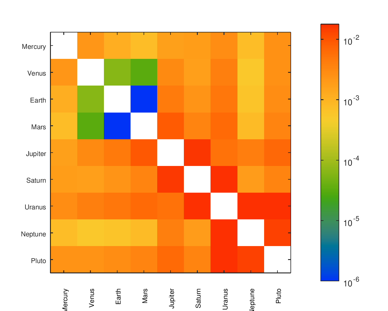
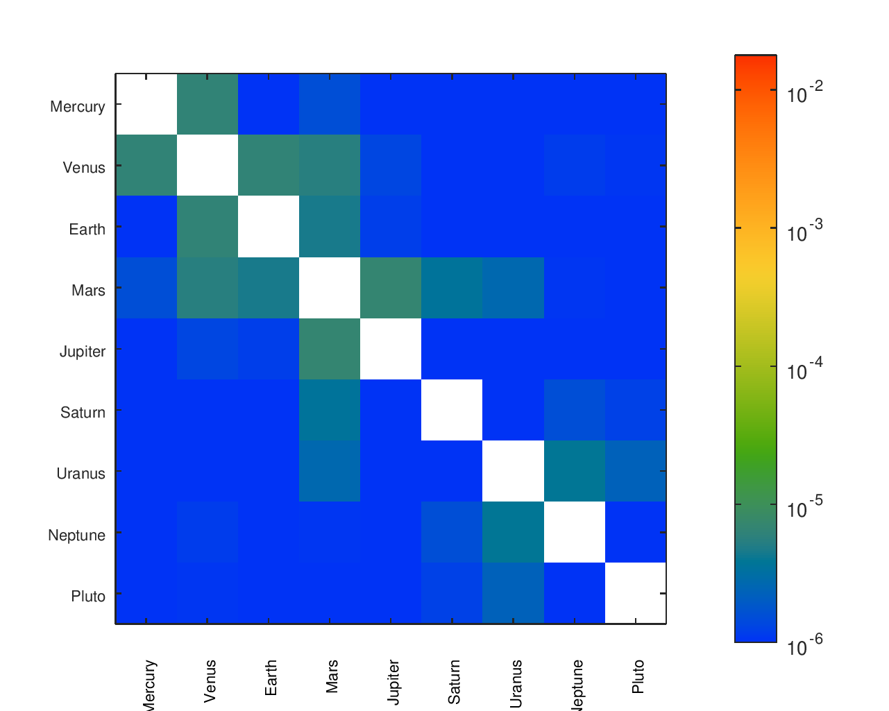
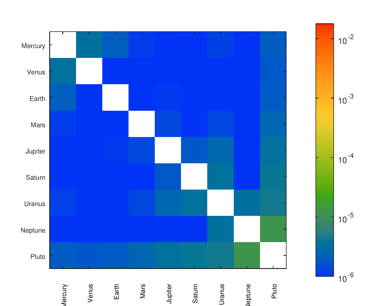
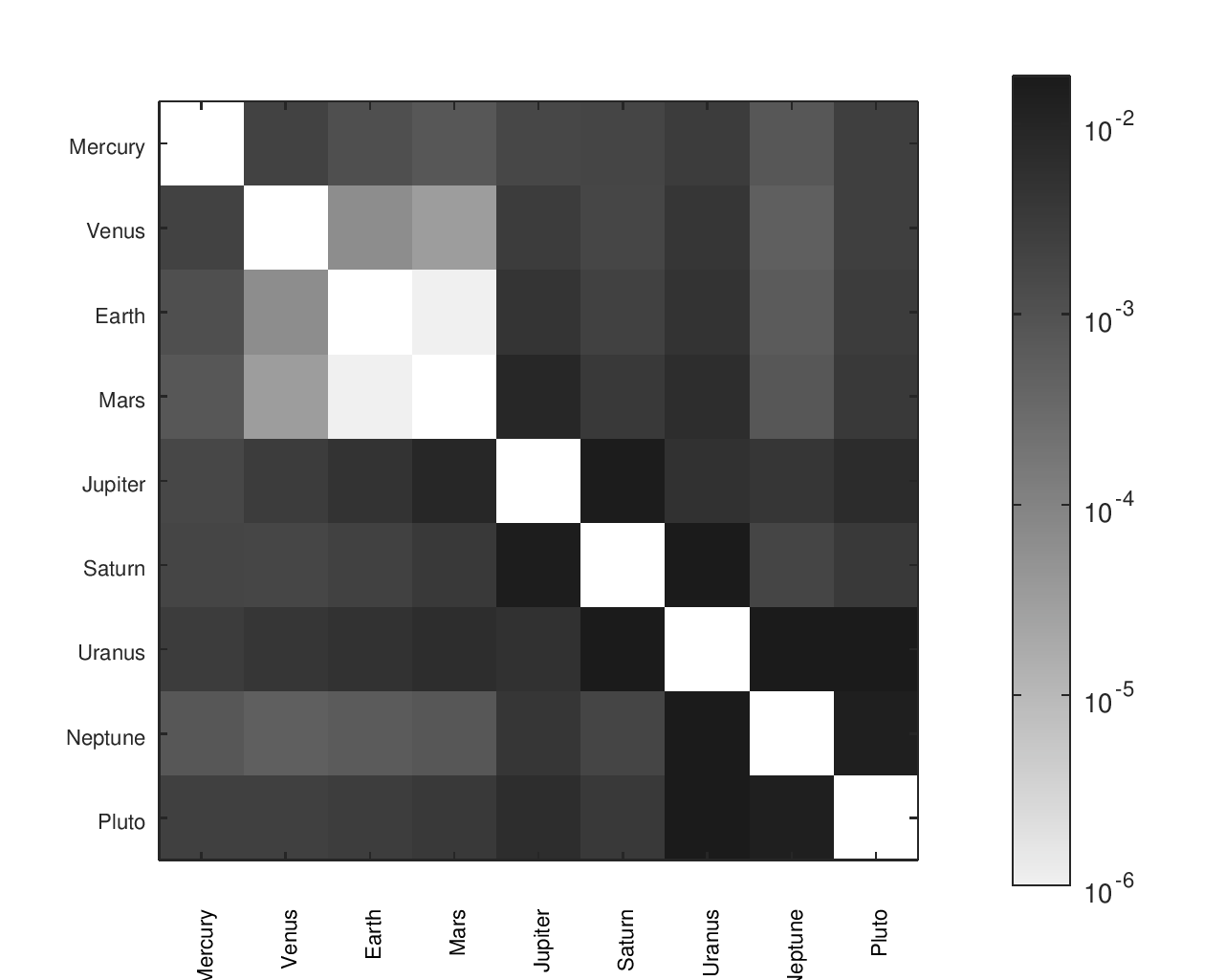
I cared not just about the ratio of Earth’s speed to the speed of other planets or the accuracy of a planet relative to its neighbors. I cared about the accuracy of the movement of every planet relative to every other planet.
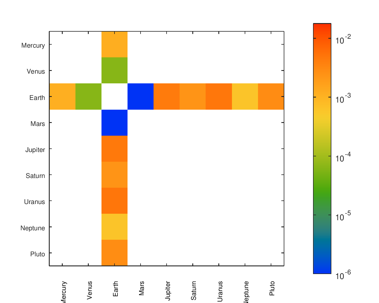
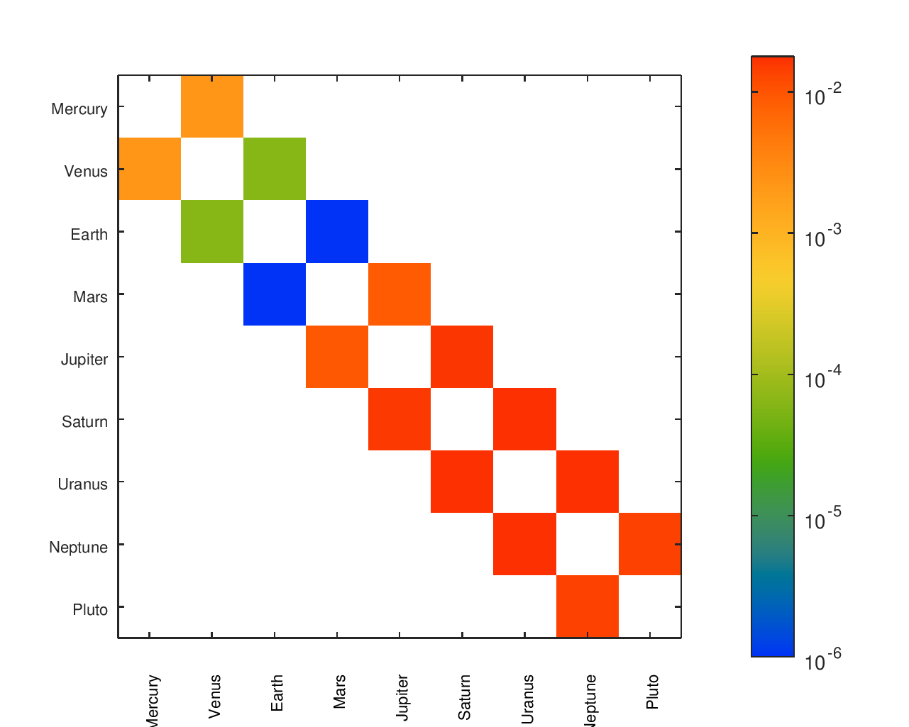
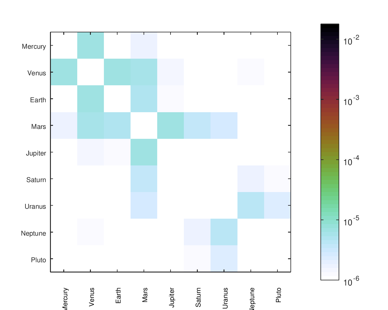
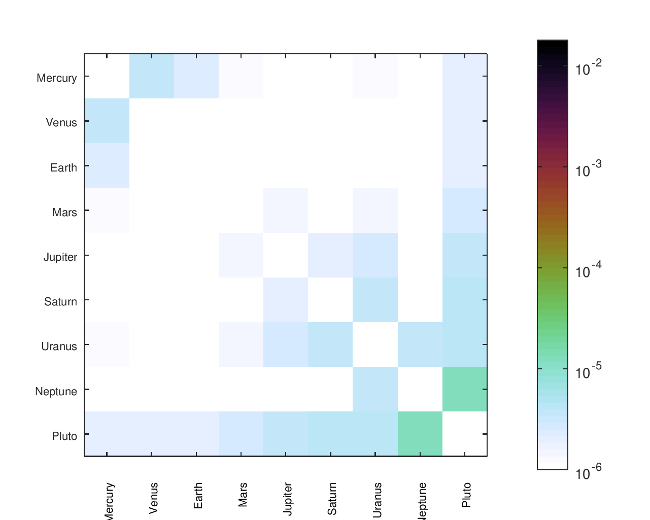
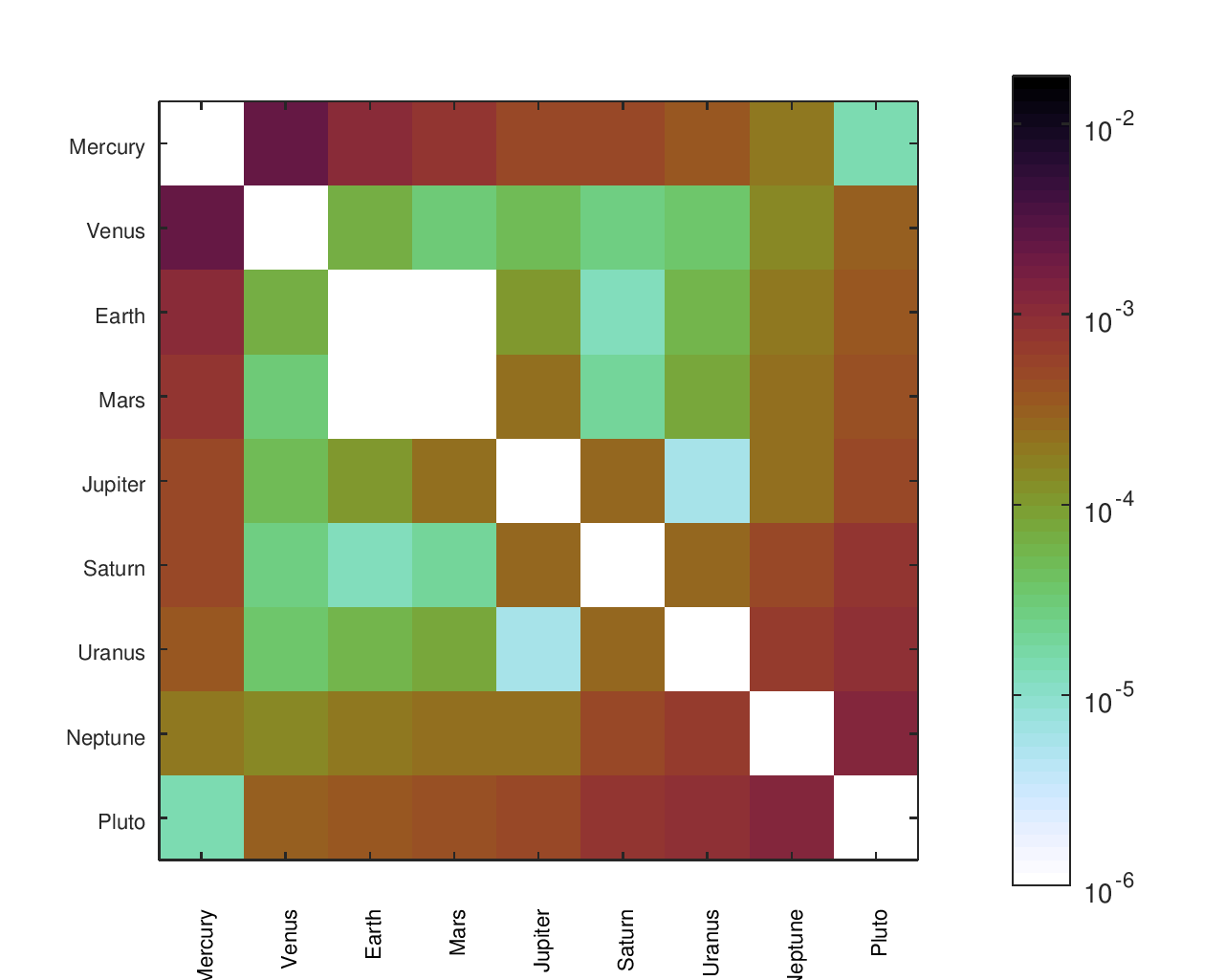
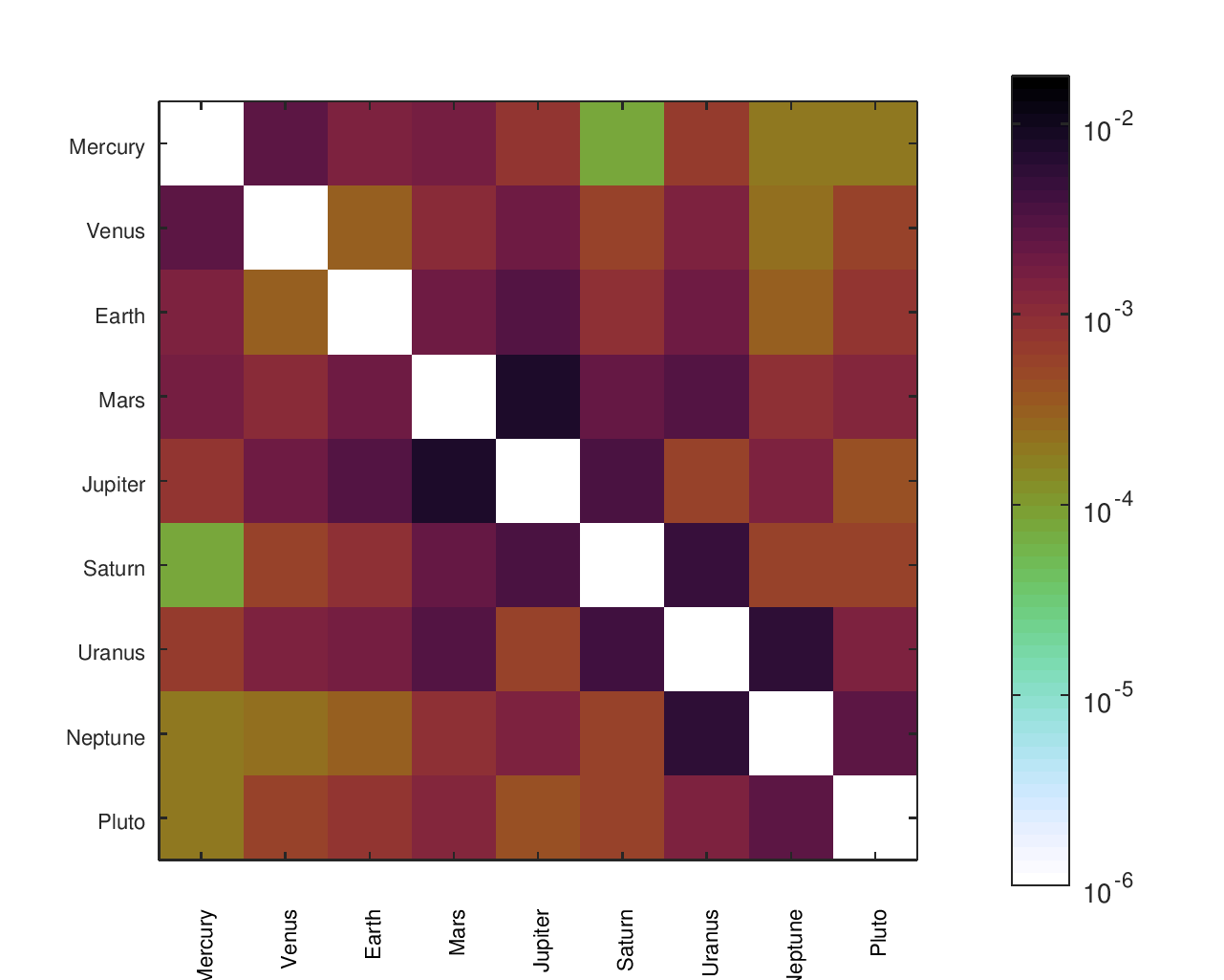
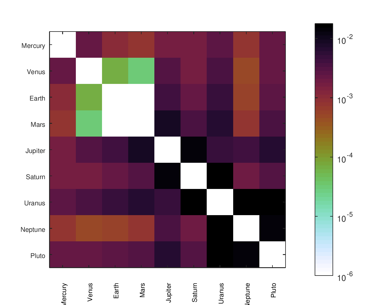
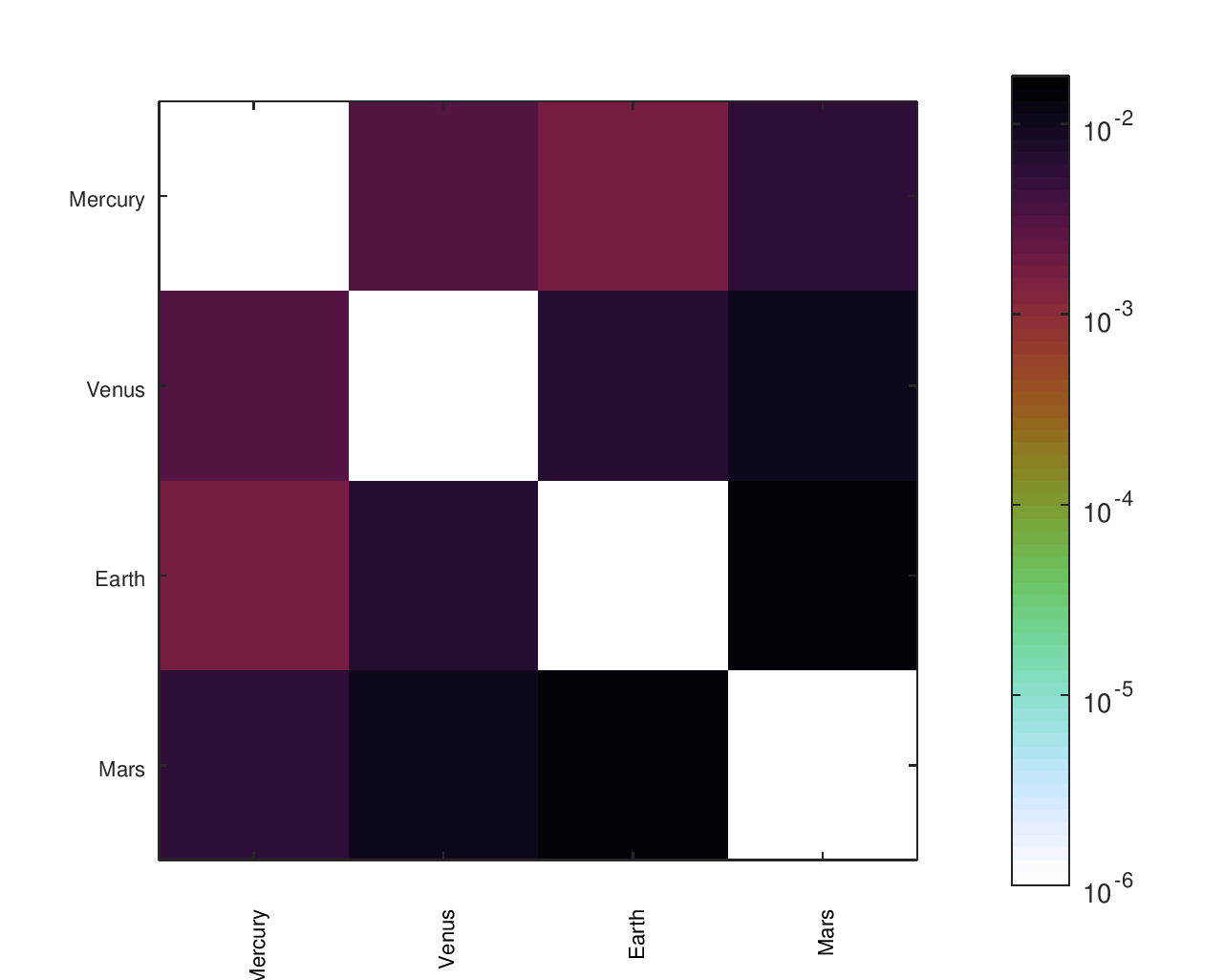
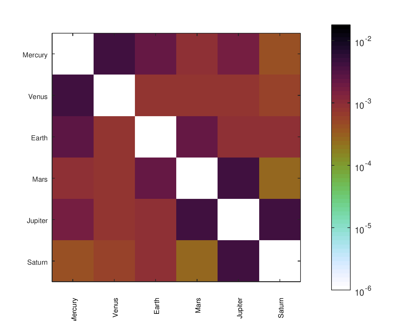
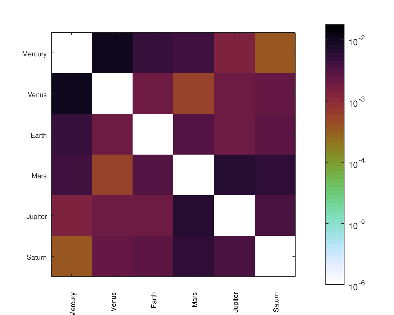
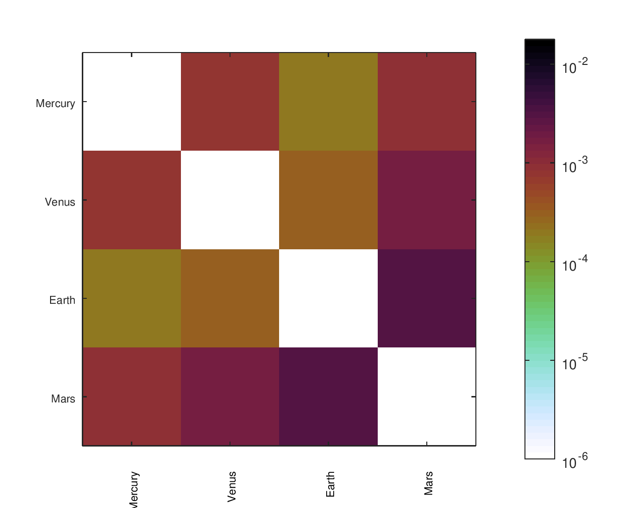
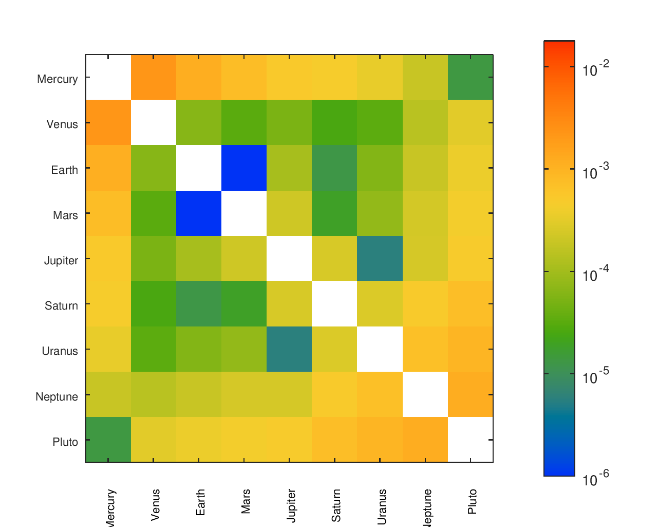
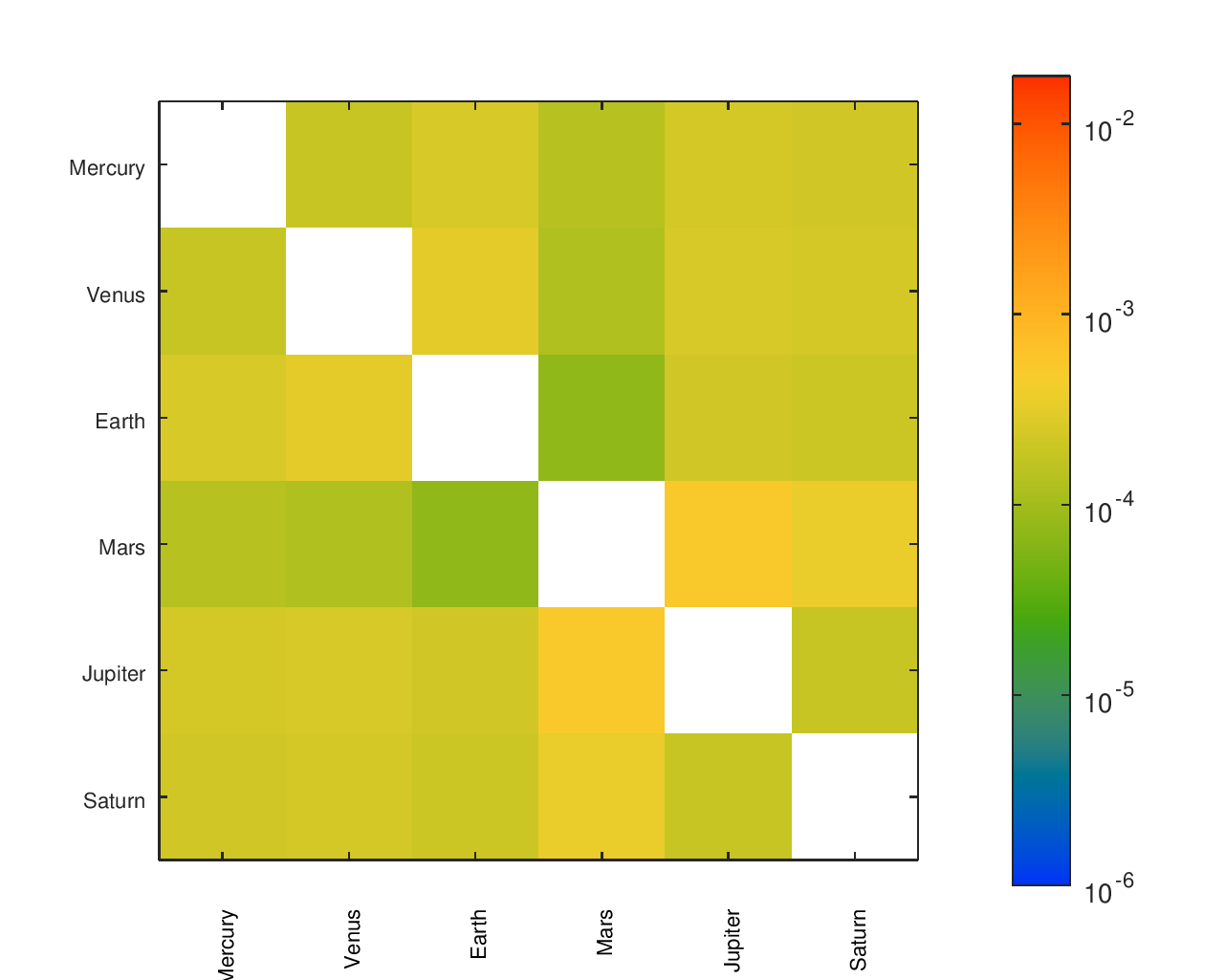
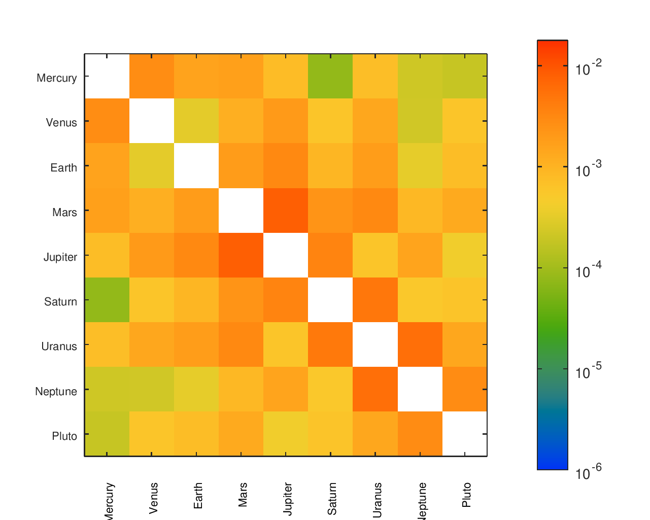
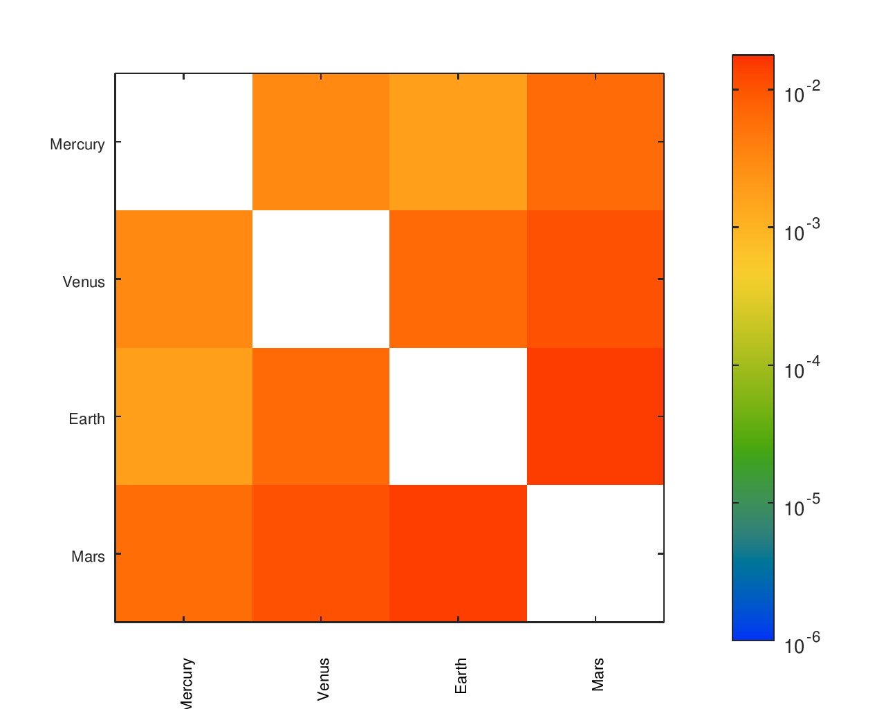
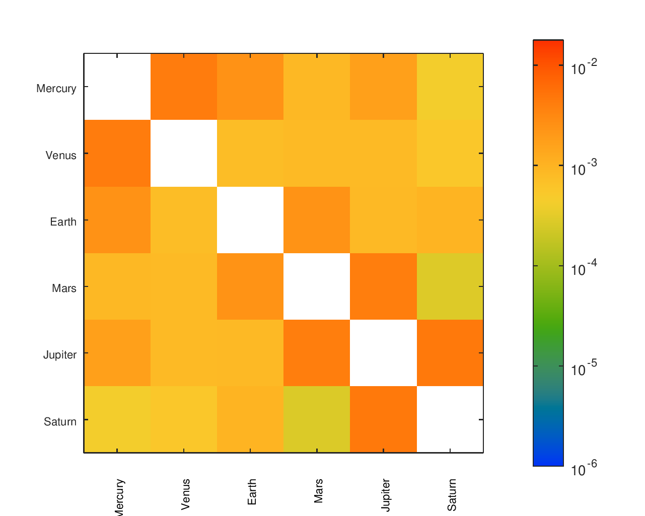
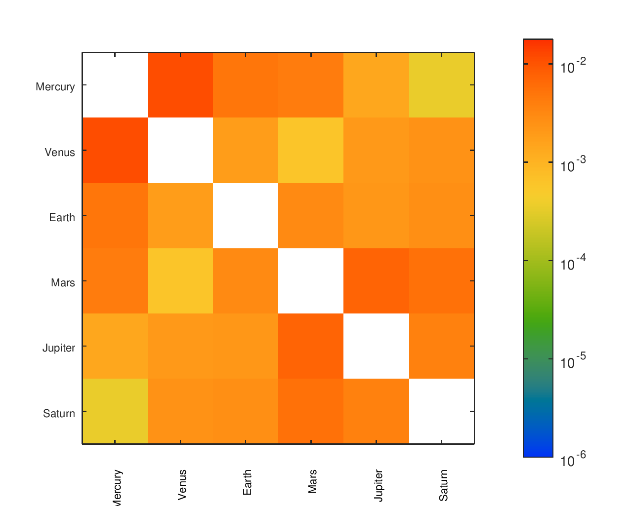
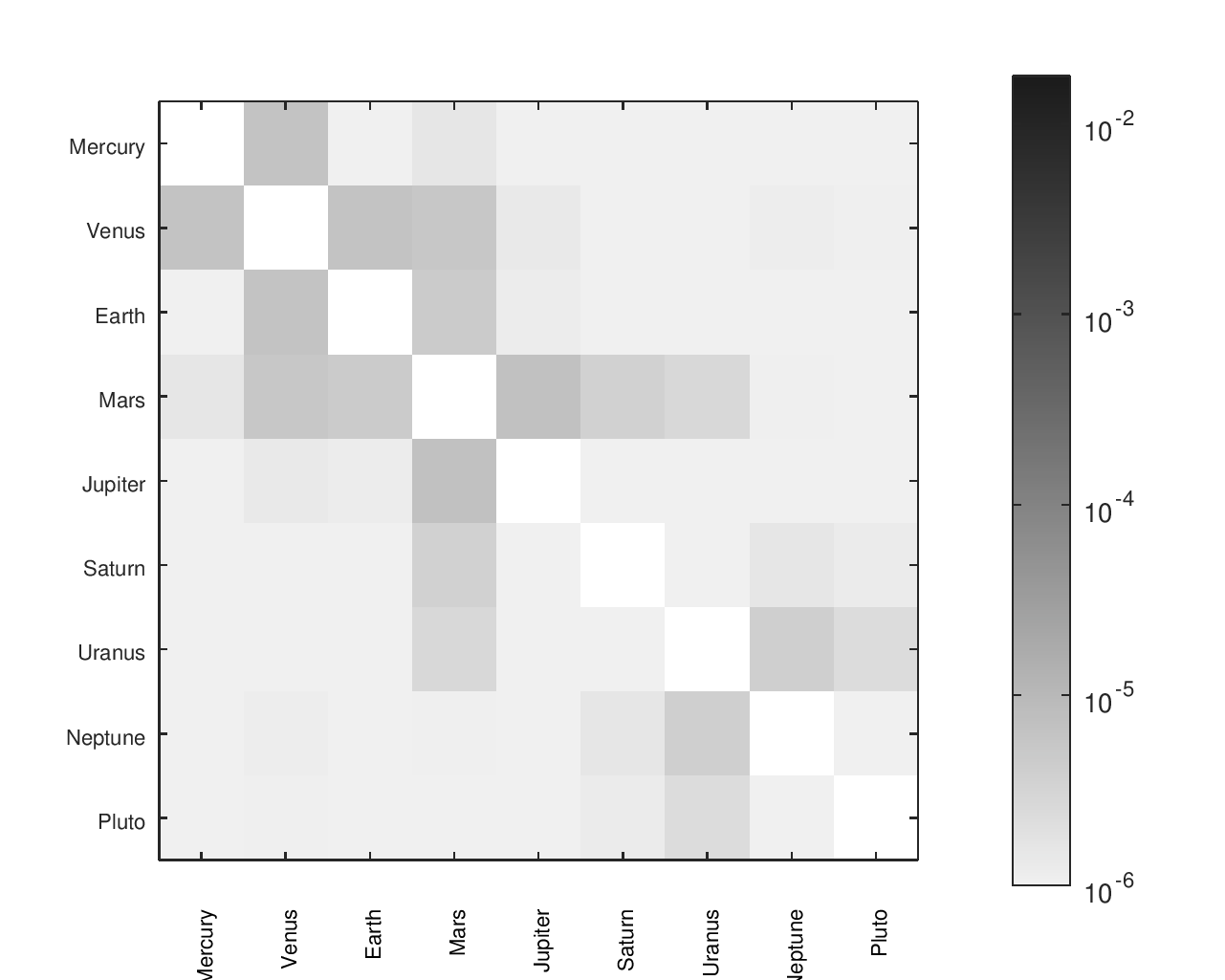
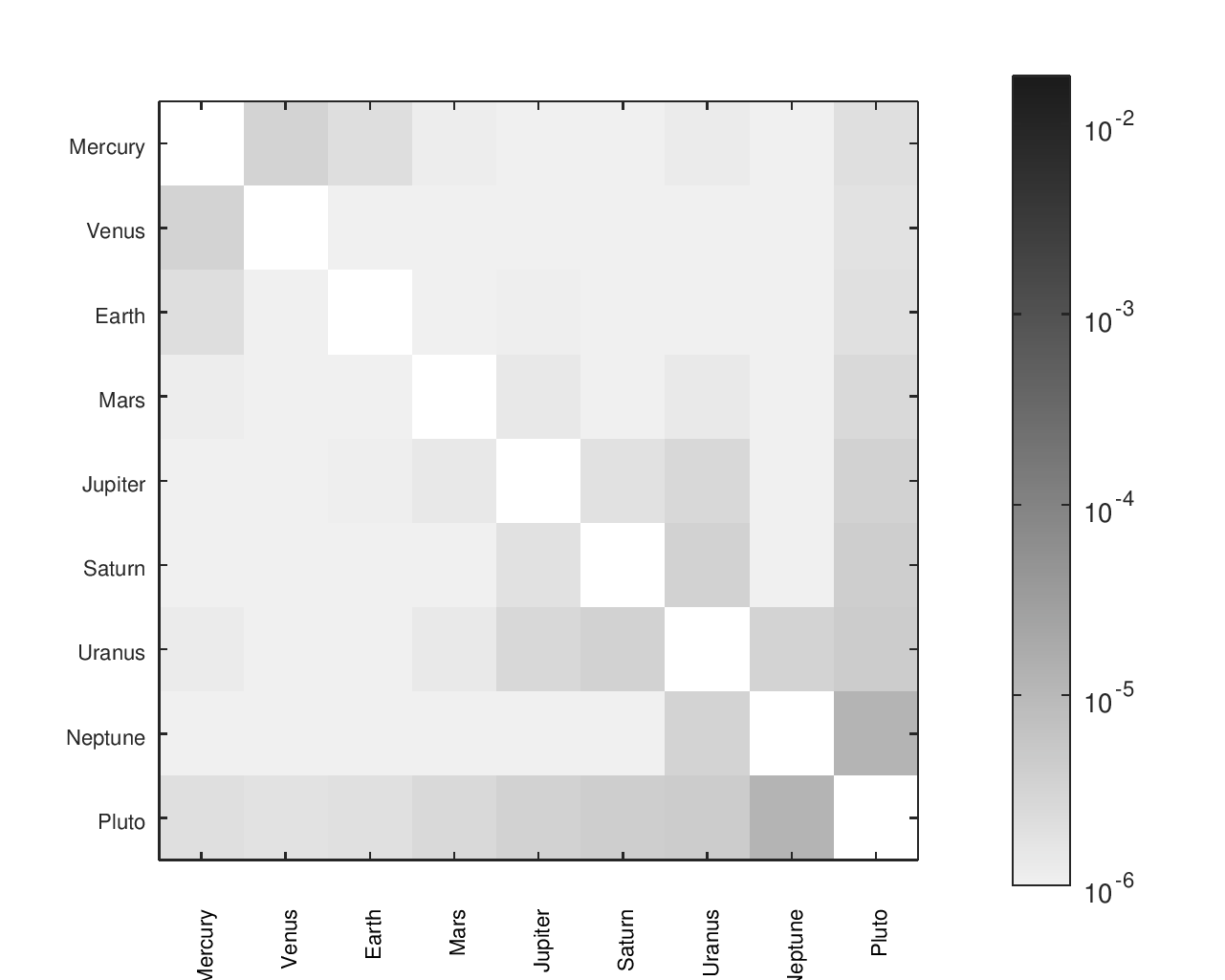
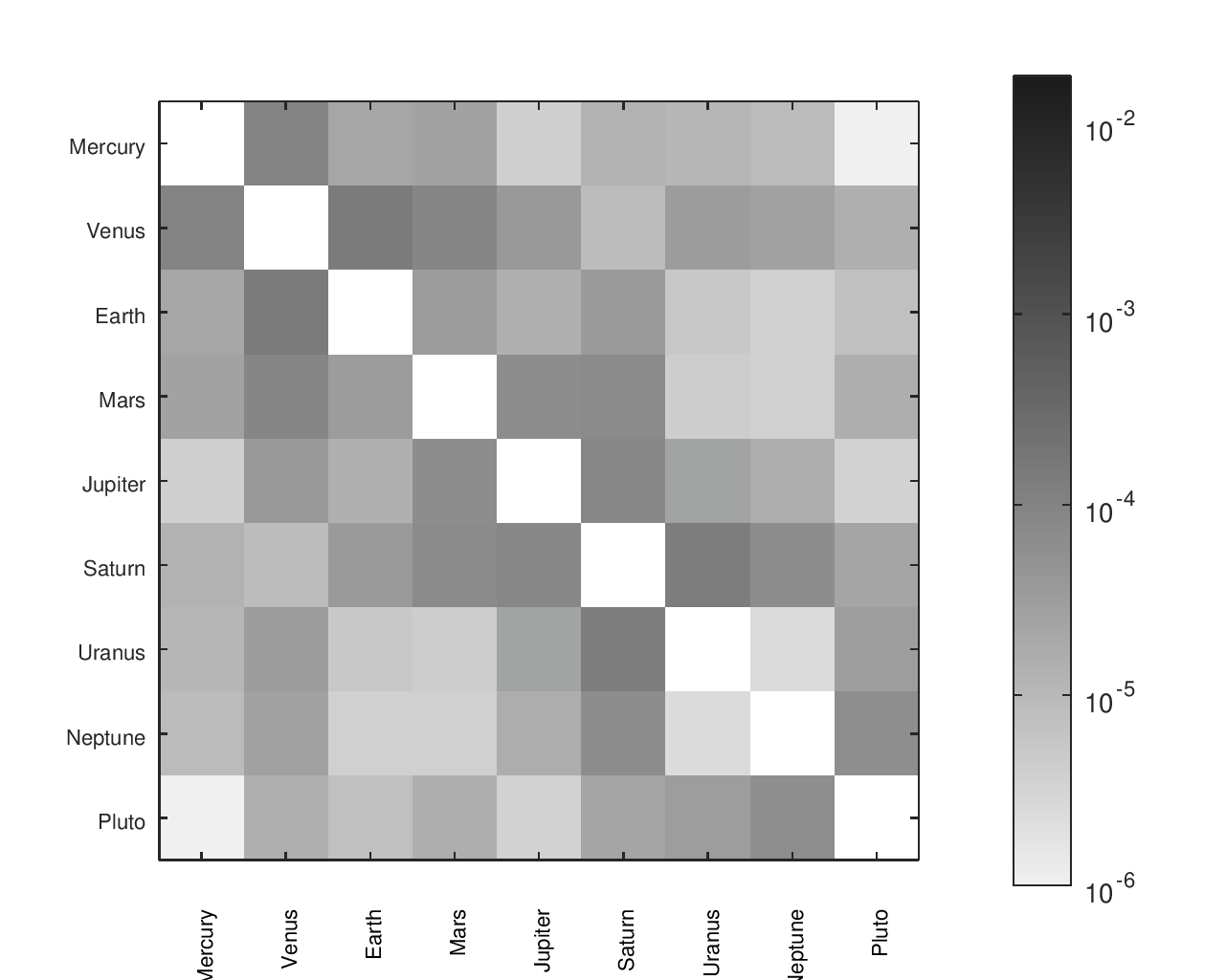
From a list of gear ratios and an incidence / adjacency matrix representing a particular tree, I had a script that would complete a matrix with the effective ratios between any node and any other node. There was a similar matrix with the desired ratios, allowing an error to be computed for each planet pair. I found that heatmaps were an effective way to visualize the location and size of those errors.
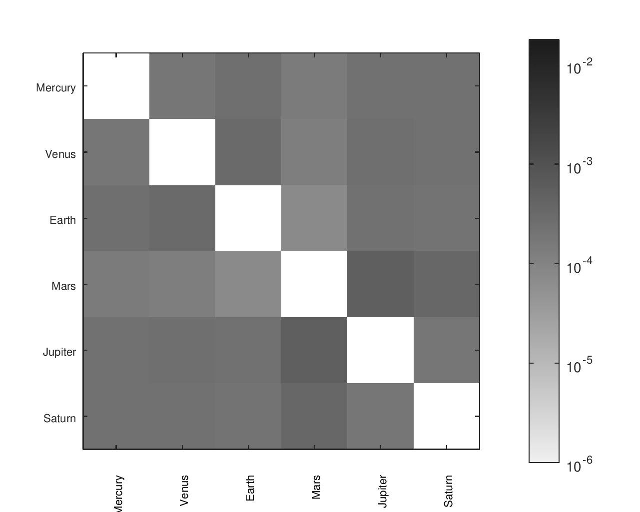
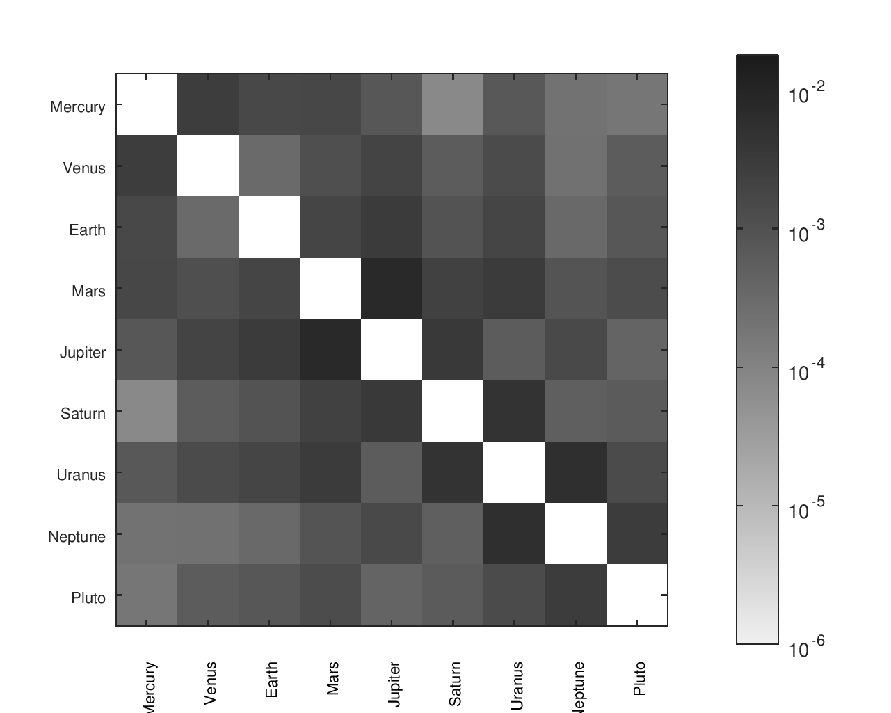
The below heatmaps show the same gear ratios' accuracy analyzed in three different ways. The first heatmap shows the type of information available by just looking at the accuracy of the planets' movement relative to Earth. The second heatmap considers the planets' movement relative to their neighbors; the results appear much different than the first assessment. The final heatmap provides a more complete picture of the accuracy of the planets' motions.
Accuracy Heatmaps & Comparison to Reference Designs
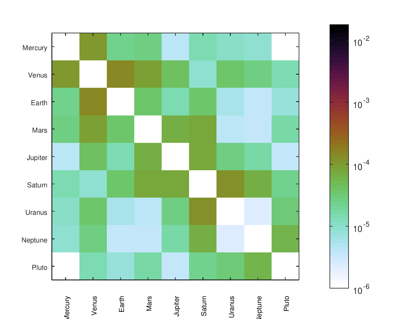
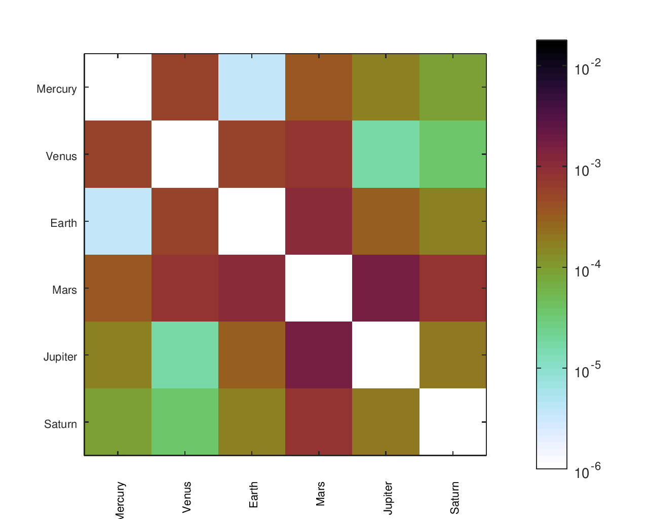
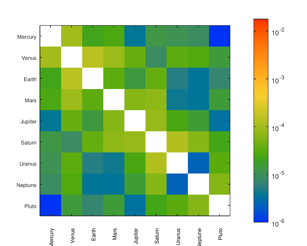
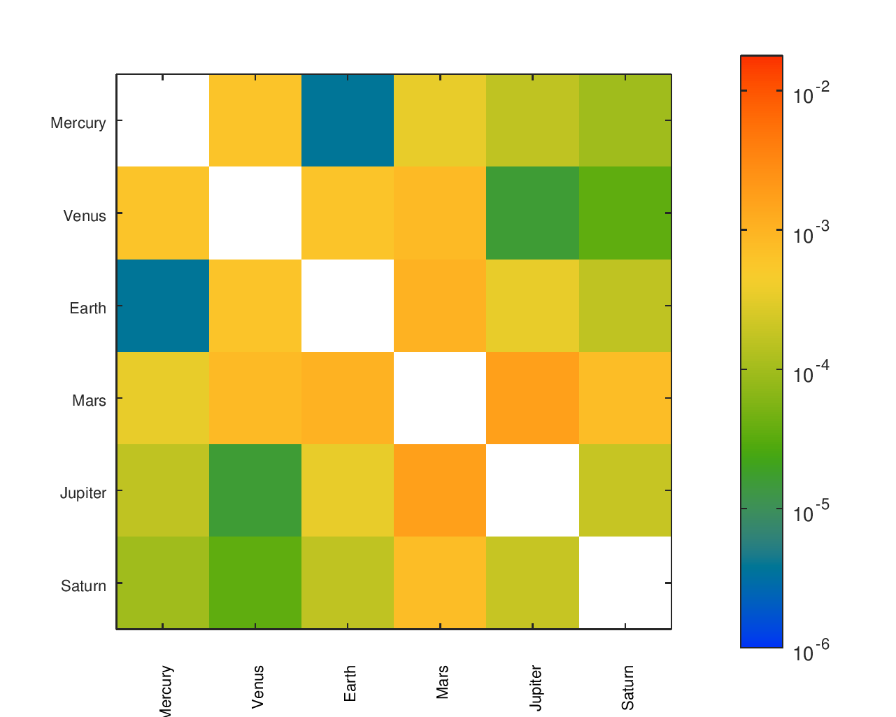
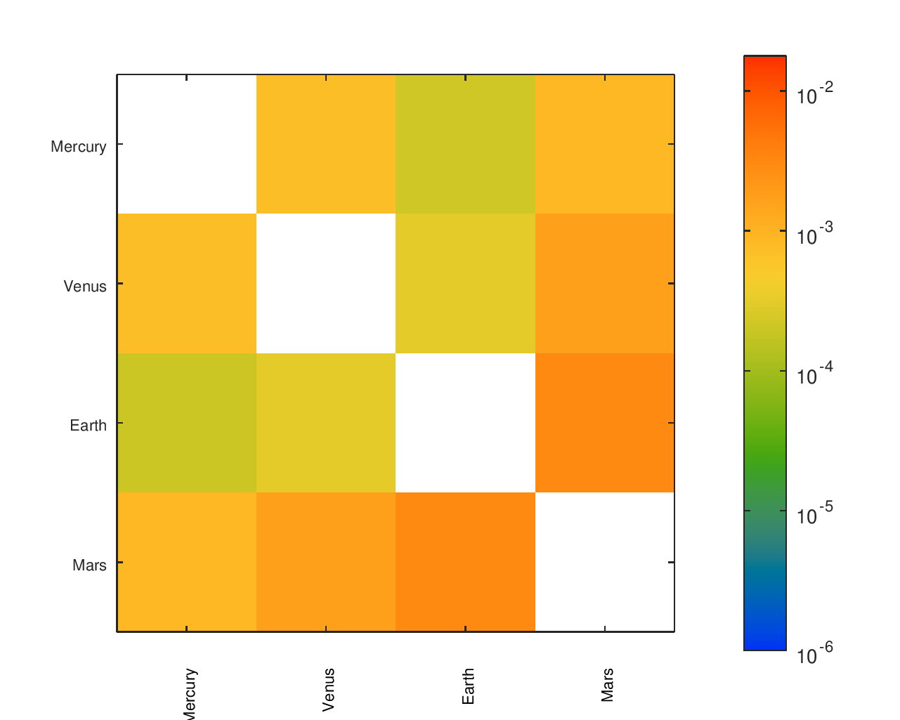
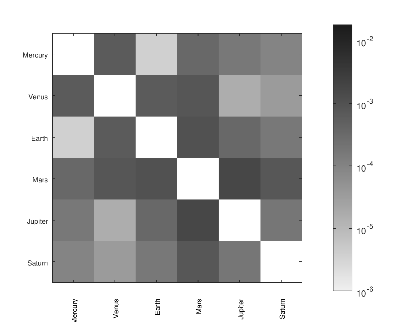
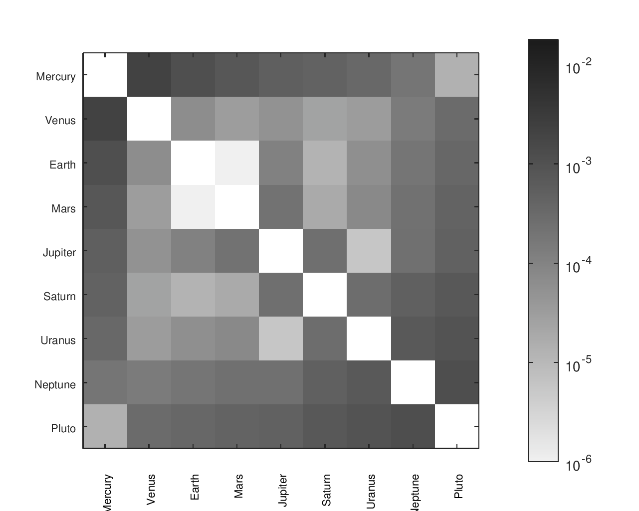
I found a number of other designs14, some of which had documented gear ratios. In a small number of cases, it appeared like a gear ratio was accidentally inverted; in those cases, I gave them the “benefit of the doubt” and corrected it for them to improve their accuracy. The names I gave to each design and their sources are in the below table.
| My Label for the Orrery | Source of Reference Ratios |
|---|---|
| Andrews Hall | I was emailed a Dropbox link by a member of the project team. |
| Yvo de Haas / Dragonator | Instructables: Solar System Orrery (3D Printed) |
| Mike Shuter (Option 1) | Distributed in 2009 by Adam Cooper |
| Peter Grimwood | “A modern planetarium and orrery,” Bulletin of the Scientific Instrument Society, no. 43, pp. 24–26, Dec. 1994. |
| Pat Briggs | Figure 5 from M. Whiting, “Orrery developments: the use of meccano in constructing planetaria,” Bulletin of the Scientific Instrument Society, no. 94, pp. 26–30, 2007. |
| Mike Shuter (Option 2) | Distributed in 2009 by Adam Cooper |
| Roy K. Marshall | “Two inexpensive orreries,” Popular Astronomy, vol. 46, pp. 389–394, Sep. 1938. |
| Ken Condal / Zeamon | The Zeamon website and a Ken Toonz YouTube video link to a .pdf and model of the orrery |
| Mathew’s Plywood | Instructables |
| Charles E. Balleisen | “Revised orrery calculations,” Popular Astronomy, vol. 46, pp. 567–571, Dec. 1938. |
The orrery names are shown by hovering your cursor over the heatmap images.
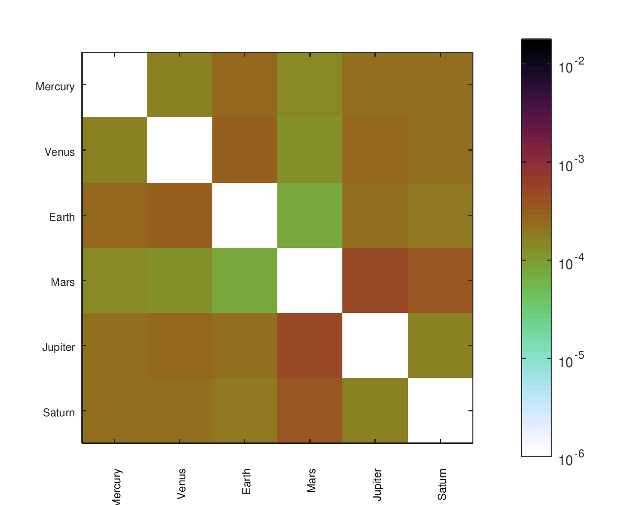
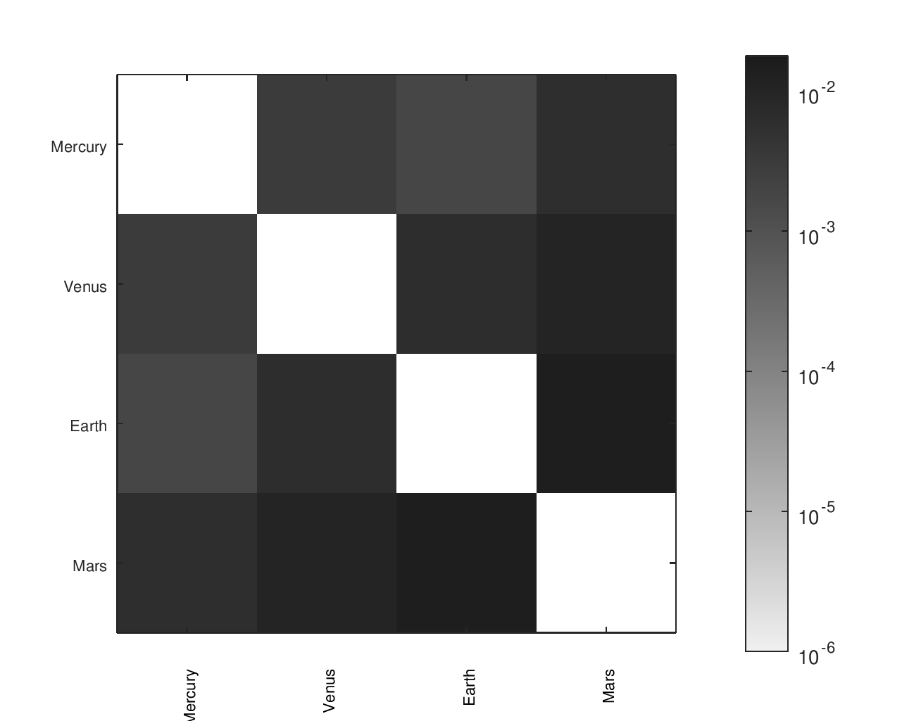
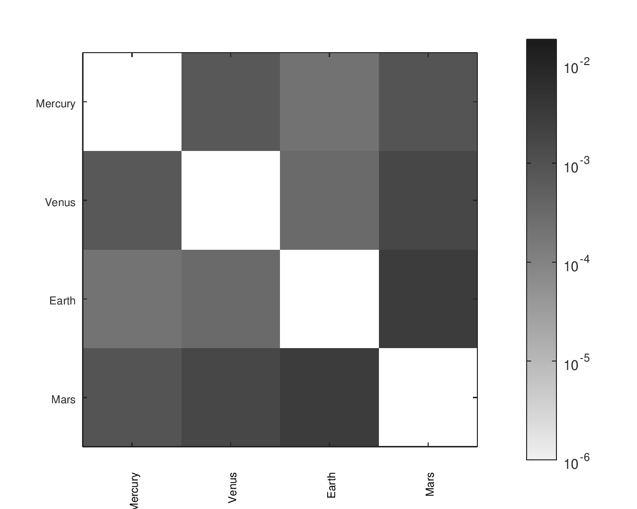
Some designs only include a subset of the planets I included in my orrery, which is why their heatmaps have fewer regions. Clicking on any heatmap should open a larger version of that heatmap.
Cubehelix Heatmaps
This is sort of an extension of the linear grey colormap. Dave Green created the cubehelix color scheme15 which is based primarily on saturation (black to white), onto which a cycle of colors is added. If it is printed greyscale, a continuous gradient is still present. Personally, I find it is easier to differentiate between close values with this than with greys because the color supplements the brightness information. Although cubehelix heatmaps have significant advantages, the rainbow heatmaps do a better job showing that the main diagonal does not contain meaningful information.
Accuracy Heatmaps of My Gear Ratios
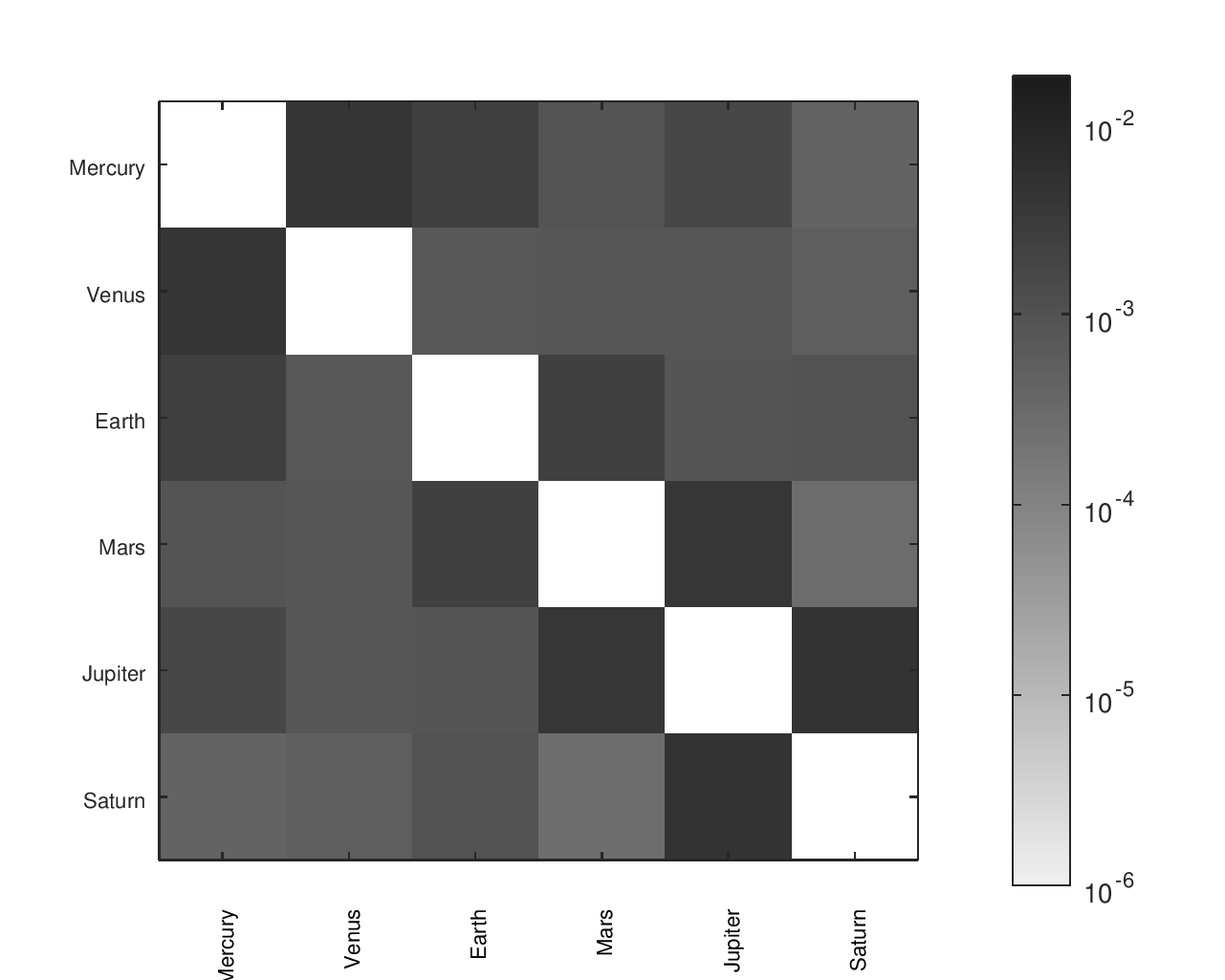
The first heatmap is for the design that I fabricated. The second heatmap is for another design I considered. The second option has a slightly better average of the ratios' errors but worse median and maximum errors. It would be a particularly attractive candidate for an orrery that omitted Pluto.
Accuracy Heatmaps of Reference Designs
Previous sections provide more details on the designs referenced and the heatmaps' construction.
Rainbow Heatmaps
The predefined rainbow colormaps commonly available (like “jet” in MATLAB) can distort how the data is perceived. For the rainbow colorations, I used a color map16 developed by Peter Kovesi at the Center of Exploration Targeting which is designed to have a perceptually uniform color space.
Accuracy Heatmaps of My Gear Ratios
The first heatmap is for the design that I fabricated. The second heatmap is for another design I considered. The second option has a slightly better average of the ratios' errors but worse median and maximum errors. It would be a particularly attractive candidate for an orrery that omitted Pluto.
Accuracy Heatmaps of Reference Designs
Previous sections provide more details on the designs referenced and the heatmaps' construction.

Greyscale Heatmaps
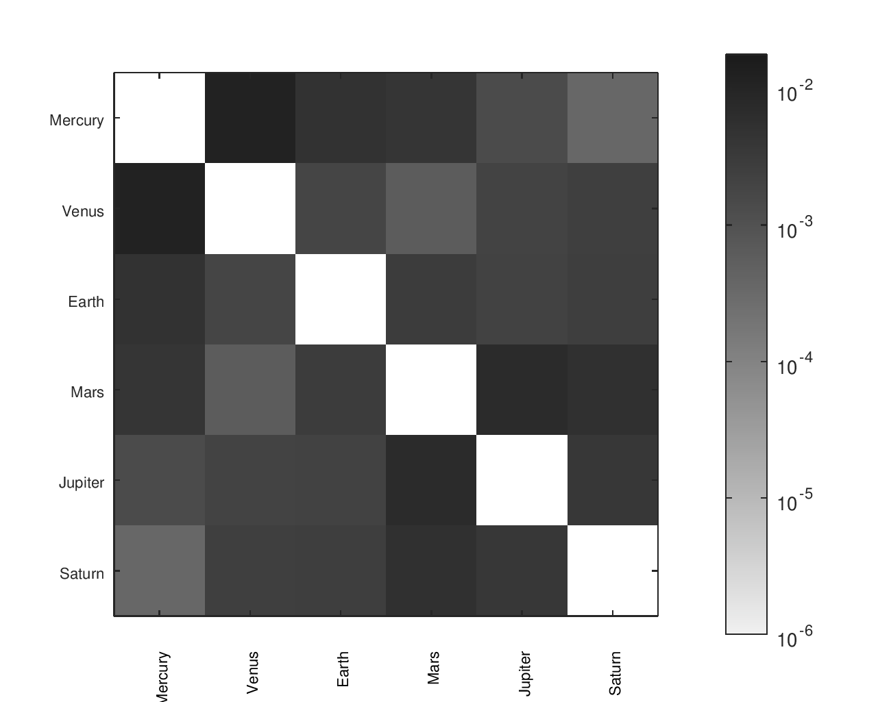
Accuracy Heatmaps of My Gear Ratios
The first heatmap is for the design that I fabricated. The second heatmap is for another design I considered. The second option has a slightly better average of the ratios' errors but worse median and maximum errors. It would be a particularly attractive candidate for an orrery that omitted Pluto.
Accuracy Heatmaps of Reference Designs
Previous sections provide more details on the designs referenced and the heatmaps' construction.
From Ratios to Parts
I considered several manufacturing options, but decided to laser cut the gears because it was cost-effective, precise, and fast (efficiently going from CAD file to usable part with minimal post-processing). I also had access to the necessary equipment and it gave me considerable flexibility in the design and options for gear ratios.
Some of the gears were large in size so I used 1⁄8 inch thick acrylic to limit how much they flexed. (Thinner sheets were tried initially.) The thicker material plus spacers along the shaft between each gear, enabled the gears to mesh successfully even with some flexing or inclination.
I also anticipated this approach would have the added advantage of being aesthetically pleasing. Clear acrylic was attractive and made the mechanism both visible and ethereal. By keeping everything visible but not too visible, it would provide some sense of the layers and complexity of the mechanism but also be somewhat mystifying and magical at the same time.
The majority of the cost of the system was the acrylic sheets and 3d printing.
OpenSCAD Model
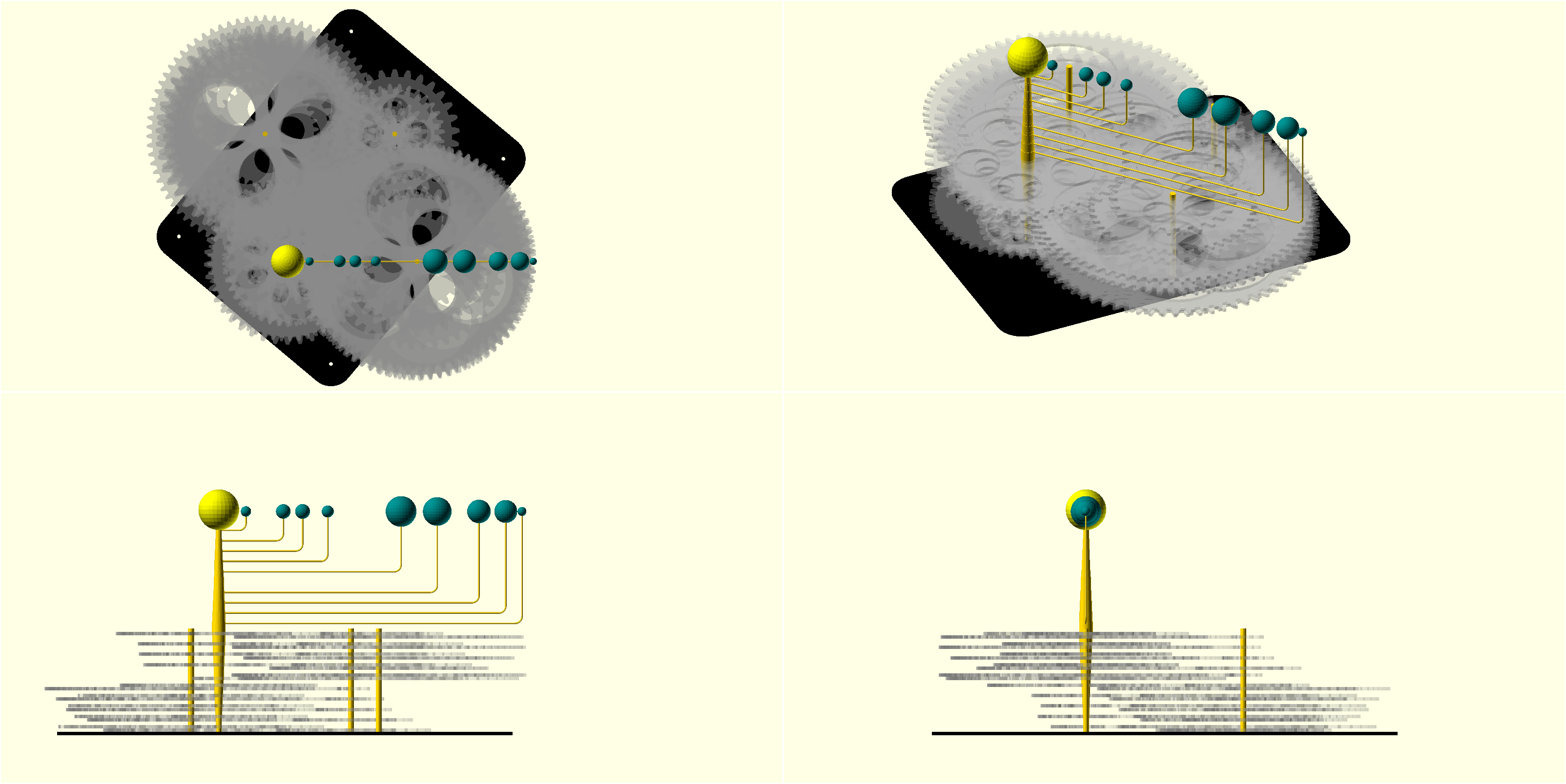
The sheet stabilizing the axes is hidden in these screenshots so the gears can be better seen. The gears were defined and calculated using lists of parameters. As seen in the System Design section, there were a total of 5 axis locations. This model aligns the two auxillary axes to save space. MATLAB/Octave would produce a list of the gear ratio pairs for entry into OpenSCAD. A matching list of axis identifier pairs was also entered (to specify at which axis the gears would be located).
OpenSCAD had two major disadvantages.
- It is slower to design with than commercial modeling tools, leading me to simplify some modeling (omitting details like the threaded rods and nuts and cotter pins). Some unmodeled hardware nearly caused problems during assembly, but I thankfully included enough clearance that things did fit.
- Any changes required the entire model to be recomputed; this was annoyingly slow.
OpenSCAD had five primary advantages:
- It ran on my Linux computer.
- It was free.
- It works well with git, which allowed easy diffing and change tracking.
- There were community-contributed online resources to build upon.
- I could control it programmatically.
Build Automation and Version Control
Using a Makefile and OpenSCAD’s command line interface, I could create a model of just the gears (suppressing everything else), take slices at various heights, and export these slices as vector files to be layed out for laser cutting. The Makefile could also generate screenshots of the OpenSCAD model and update the LaTeX project report.
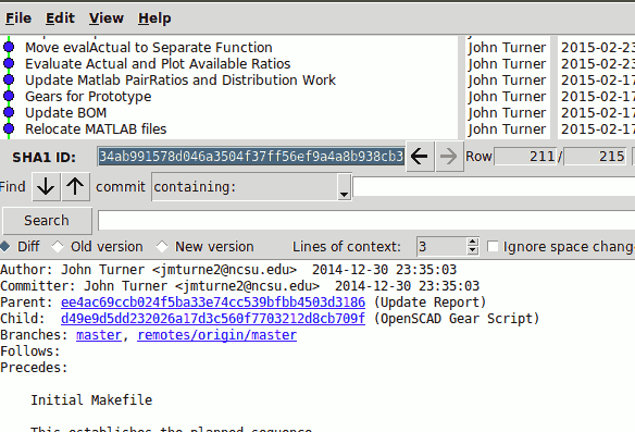
During much of the project, I also used git for version control. I tracked changes to the MATLAB / Octave scripts, the draft of my project report (written in LaTeX), and a variety of other files. Below is a screenshot of a graphical interface showing some of the revision history of the project’s git repository.
Fabricated System
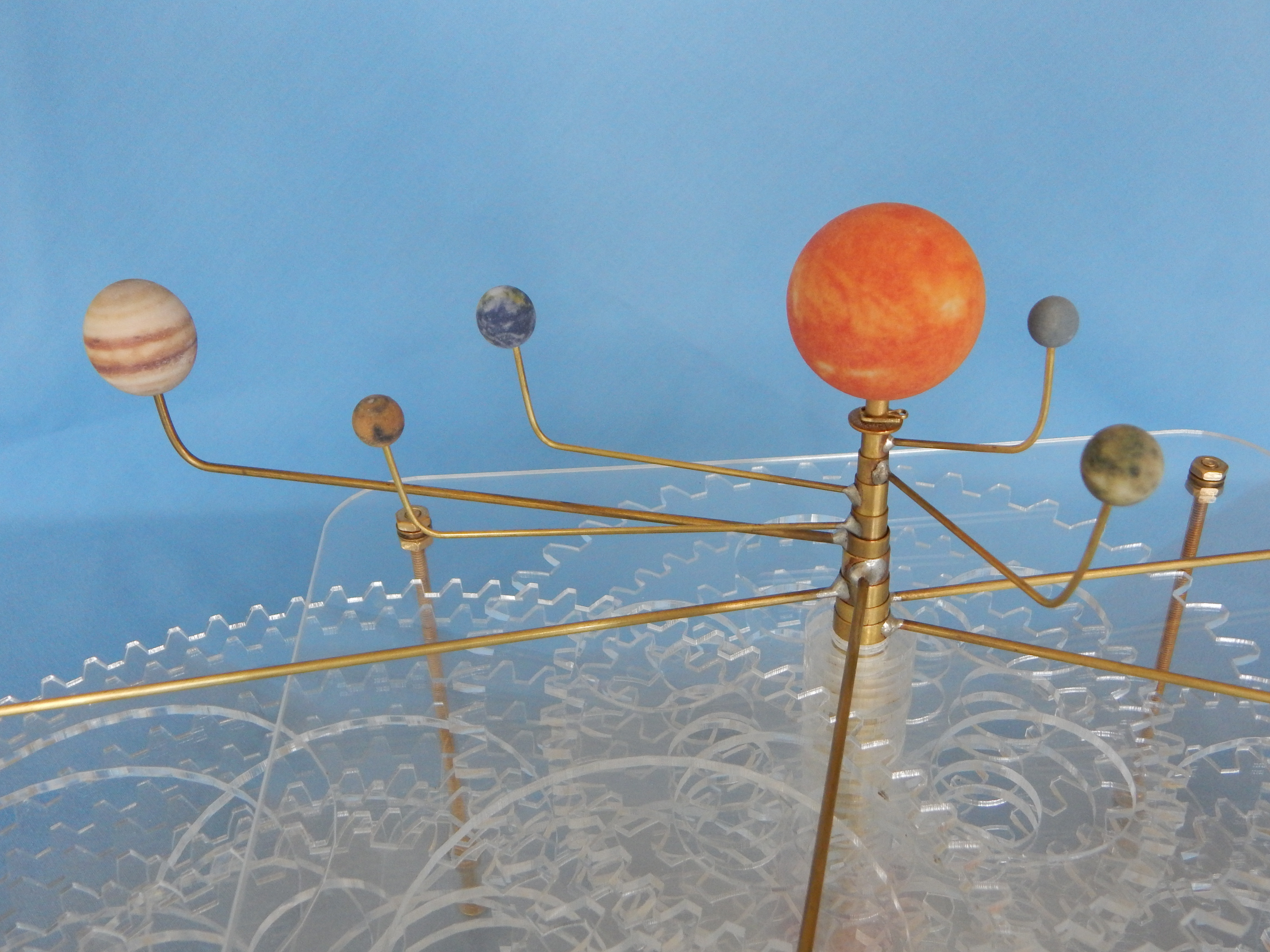
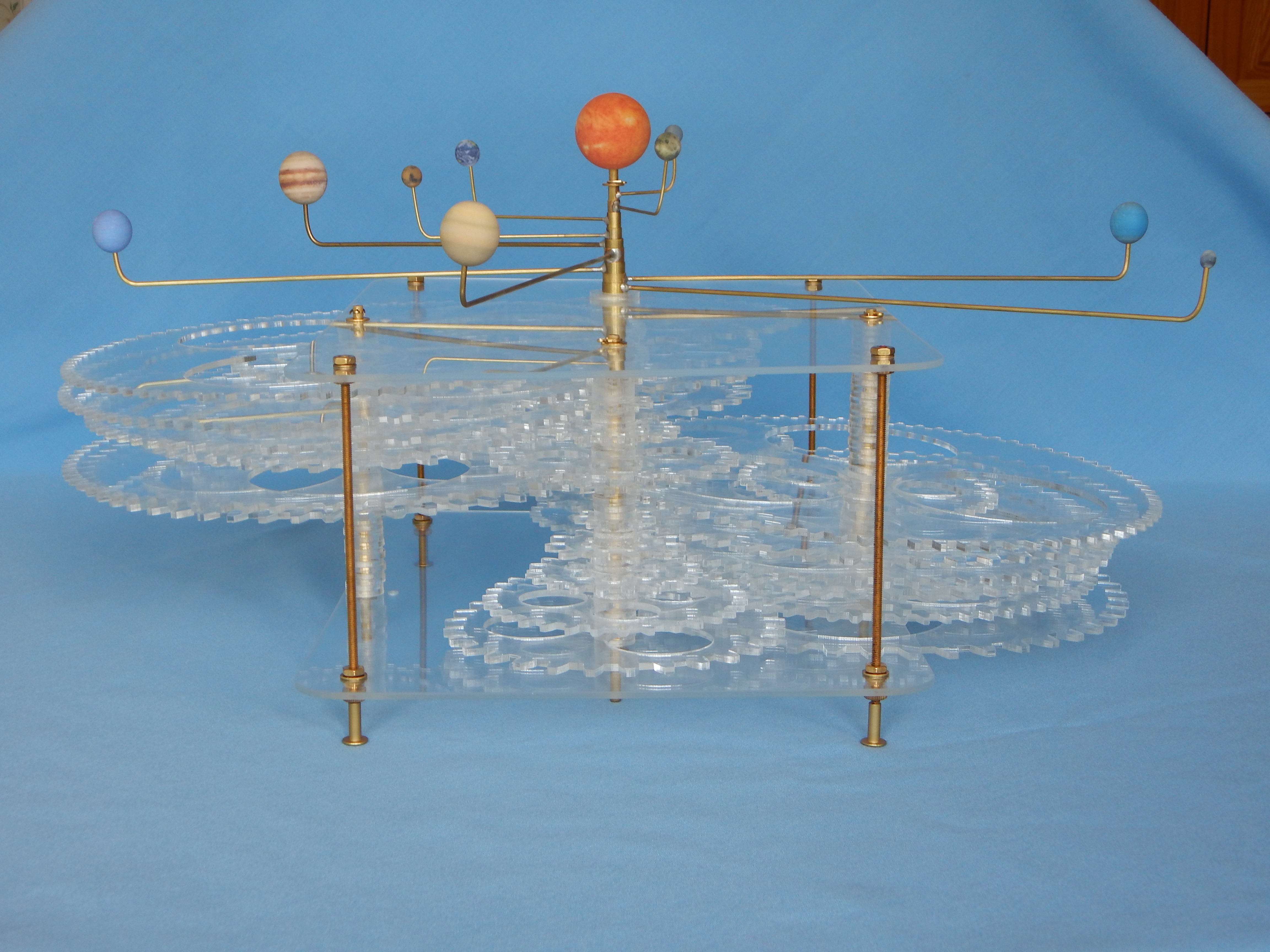
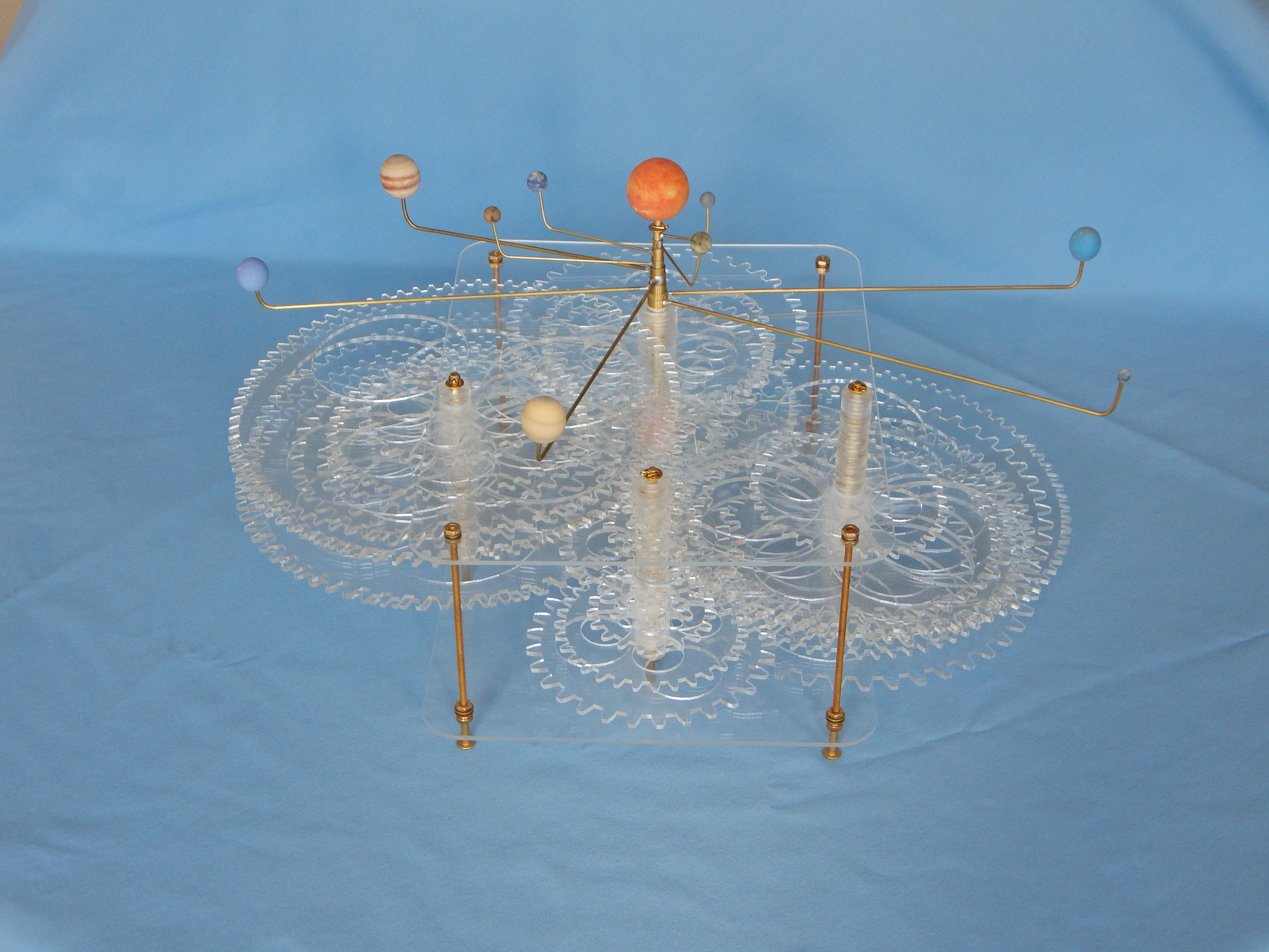
Closeup of orrery showing the appearance of the Sun, inner planets, and Jupiter. Elevation view shows the telescoping tubing used for each planet. This view provides the best illustration of the gear structure. There are four pivot locations. The planets share the back pivot location and the auxillary stacks (described by the tree in the System Design section) share the front pivot. The left and right axes contain the intermediate gears in each train connecting a planet to the auxillary axes.
Lessons Learned
Below are some observations from this project that apply to more than just orreries:
- I enjoy investing making things and being able to refine their design.
- It is tempting to spend a lot of time on things I enjoy. To keep a project on schedule, it is important to have a defined project scope and to break projects up into smaller deadlines.
- Version control is incredibly useful. Using Git, I could track my code and documentation as it evolved, comment on those changes, and easily see differences between versions. When I started my job after graduation, this experience helped me to appreciate and quickly learn SolidWorks PDM (a proprietary version control solution from Dassault Systèmes).
- I should have used Octave or Python for development instead of MATLAB. MATLAB was free as a student, but GNU Octave and Python are always free and would have sufficed for this project.
- Although the laser cutter made fabricating parts easy, assembly could be improved. Soldering was done before the gears were added. However, this increased the difficulty in keeping the gears straight during assembly and risked damage to the planet arms.
- A project will never be perfect, but it can complete an objective. If the project is well documented, it makes it easier to pick the project up again.
Footnotes
- Zeamon website’s orrery page and Popular Mechanics article show it. [return]
- Staines & Son Orrery Makers [return]
- Paul Bambrick Finescale Modelling [return]
- An article from CU Boulder Today and Eitan Cher’s portfolio show the result of the student team’s work. [return]
- While I was a student, NC State University’s Hunt Library had a makerspace in it with a laser cutter, 3d printers, and other equipment. The library’s makerspace has now expanded to serve both campuses with more equipment. [return]
- Burke Brothers Hardware has been serving the Raleigh area since 1936! They had a particularly good in-store selection of telescoping tubing and rods from K&S Precision Metals and miscellaneous brass parts. [return]
- Personally, I used a vendor on Shapeways (1, 2) as the source of my planets, but the vendor was not selling a sun. I extrapolated the logarithmic scale from the planets for a separate Shapeways print of the sun; NASA’s STEREO mission was the source of the sun imagery. [return]
- There are a variety OpenSCAD scripts for gears, although some may struggle with specific geometry like undercuts. I used Greg Frost’s involute gear script but modified it to support stub gears. Unfortunately, the quality of the cut gears was not as good as I had hoped. Involute gear teeth are often constructed from a sequence of straight line segments, but Bezier curves might provide a smoother approximation. Unlike OpenSCAD, Inkscape supports Bezier curves natively and can save them in .svg files (used by the laser cutter). It is also possible to write scripts for Inkscape. This should produce much smoother laser cut teeth profiles without resorting to large numbers of straight lines. Although OpenSCAD does not support Bezier curves natively, it could still use the gears from Inkscape if one of a couple scripts (1, 2) handle the Bezier curves. Although there is a script for entering Bezier curves in OpenSCAD, they do not remain as true Bezier curves when rendered, exported, or converted to other formats. [return]
- It would have taken me far longer to write automated packing software than it did to manually arrange the parts to be laser cut. Commercial nesting optimization software does exist to help automate this and maximize material efficiency, but I wouldn’t have used it enough to justify the cost (several thousand dollars in some cases). Now, there are also free tools to help with shape packing; DeepNest is one such open source and cross-platform tool intended to help lay out parts for laser cutting. [return]
- The sidereal periods I used can be found in a variety of places: 1, 2, 3 (found here & here), 4, 5, and more. This type of information is calculated from ephemerides which are produced by numerically integrating the equations of motion from some initial conditions. Differences can result because the orbits are derived from different data sources and for different spans of time (see this forum discussion and Wikipedia page about the JPL Development Ephemeris (DE)). Some of the other orrery designs could have been or were based on a different period values, like those found in Table 12.1 of Allen’s Astrophysical Quantities, 4th ed.. The Hillis orrery design specifically states that it was based on values “derived from an extended form of the JPL Development Ephemeris 422 (DE422)” with a “10,000-year interval of interest (02011-12011).” “If a different timespan was considered, slightly different values would result.” [AAS 11-665] [return]
- Exact mathematical quantities “can be considered to have an infinite number of significant figures.” Counts and conversion factors are given as common examples of exact numbers with infinite significant figures; for the gears, the counts of teeth would be exact and the ratio of these counts would also be exact. [return]
- When I originally completed the project, the error was calculated by dividing the difference of the selected/possible gear ratio and the desired gear ratio by the desired gear ratio. This was used during the design optimization and is used by the graphs on this page. The worst case for this error definition, given a list of possible gear ratios, would be when the target ratio is the arithmetic average of the two adjacent possible gear ratios.
If I were to revisit the project, I would investigate using the percent error of the logarithms of the gear ratios instead. This would make the worst case instead be when the target ratio is the geometric average of the two adjacent possible gear ratios. [return] - Unfortunately, although some Scientific Instrument Society Bulletins may be available online, the bulk of their archive is available to SIS members only. I suggest starting with Bulletins 82, 94, 97, and 106. You could try asking your library if they can get copies for you. [return]
- There are numerous other orreries in existance. Astronomy: Globes, Orreries & Other Models), Phil Sydor’s website, and Astronomische Uhren und Welt Modelle der Priestermechaniker are more extensive than this page, particularly for historical designs. [return]
- Dave Green’s has a webpage discussing his cubehelix scheme. I used Stephen Cobeldick’s implementation. [return]
- Peter Kovesi has a webpage and article (Good Colour Maps: How to Design Them) talking about color maps. Conveniently, he provides an MATLAB / Octave function that contains pre-generated arrays for his collection of color maps. I used the “R2” and “L2” color maps. [return]
